


< News |
28.06.2014
Air-Source Heat Pumps
A breath of fresh air
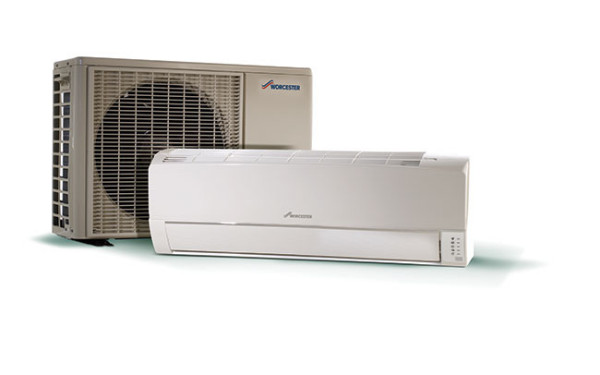
Air-to-air heat-pump technology offers a cost-effective source of healthy air. Martyn Bridges, director of marketing and technical support at Worcester Bosch, offers a step-by-step guide to the Greensource system.
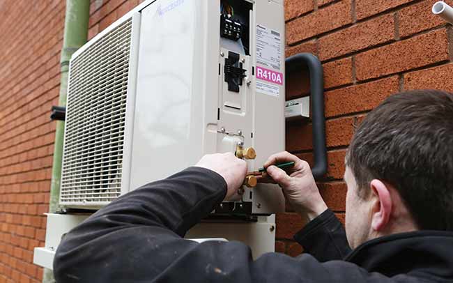
To begin, it’s important to find a suitable site to mount the Greensource outdoor inverter unit. It is worth keeping in mind that the unit’s location should be far enough away that outgoing air and operating noise do not disturb the homeowner or neighbours.
Once happy with the chosen site, position the outdoor unit according to the installation instructions. The Greensource air-source heat pump can be mounted onto a wall or directly onto the floor. Allow a minimum of 200mm clearance around the front of the appliance and provide as much installation space as possible for efficient air movement (Figure 1).
Next, install the external wall bracket. This is done by placing the mounting plate horizontally on the wall, allowing 50mm clearance on both sides and marking the location for the wall plugs and the tube hole. Then drill the 6.5mm diameter and 32mm depth holes and fit the wall plugs (Figure 2).
Secure the internal mounting plate in the seven places and check it is firm (Figure 3). Drill a 70mm diameter hole, to hold the electrical cables and refrigerant pipework, with a 5mm downward slant to the outside. Set the sleeve and caps.
Once the internal mounting plate is secure, connect the electrical cable to the indoor unit. Open the panel by about 70° and remove, and retain, the screw from the indoor unit. Connect the electrical cable, ensuring that the markings on the indoor unit’s terminal board match those of the outdoor unit.
Be careful not to confuse the terminal connections as wrong cabling may damage the internal control circuit. Fix the cable with the cord holder and replace the retained screw.
Mount the indoor unit to the wall. Pass the auxiliary pipe and the drain hose through the piping hole and hook the unit onto the mounting plate. Push the unit and apply the bottom hooking points to the mounting plate’s support. Check it is fixed in place by gently pulling the bottom of the unit (Figure 4).
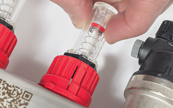
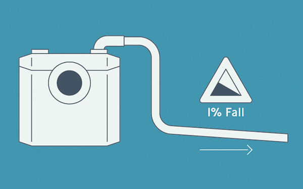
Connect the refrigerant and drain hose pipes* by flaring the end of the refrigerant pipe in order to make the connection. Lay the drain hose vertically to ensure a smooth drain flow with no traps. Tighten the pipes by hand for the first three to four turns and then use a wrench or torque spanner. Wind coating tape around the refrigerant pipes together with the drain hose and the electrical cable (Figure 5).
Next, insulate the refrigerant pipes and drain hose. The thermal insulation should cover both the gas and liquid pipes, using class O insulation (6mm or thicker).
Connect the refrigerant pipes and the electrical cable to the outdoor unit. Prepare the end of the electrical cable and remove the control-box cover. Remove the cable holder and connect the cable, ensuring the terminal connections are as specified. Remember to take care when dressing the cable so that the control-box cover, the cord holder and cable holder are not loose to avoid any potential problems. Fix the electrical cable sheath with the cable holder and the screw. Place the control box cover back in the reverse order (Figure 6).
Prepare a dedicated power supply circuit in accordance with the IET wiring regulations. Provide an earth leakage circuit breaker and fit a disconnection switch, having a contact separation of at least 3mm in all poles to the electricity power line.
Finally, complete the installation by doing a test run. Open the panel to view the control section, then start the operation with the remote control and press ‘AUX’ for five seconds or more. You should hear a beep sound and the operation lamp will start to flash, indicating that the system is in the cooling test-run mode. To test the heating mode, simply select ‘heating mode‘ on the remote control.
It is a requirement that any work undertaken on the installation of refrigerant pipework and the commissioning thereof is only completed by an installer with the relevant F-GAS refrigerant-handling skills and qualifications
Insider tip
If choosing a floor-siting situation, the system requires a stable base and should be sheltered from rainwater, strong winds and not be in a position where the unit can be tampered with
Figure 1
Choose a
suitable external location
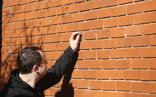
Figure 2
Install the external wall bracket
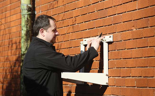
Figure 3
Secure the internal mounting plate
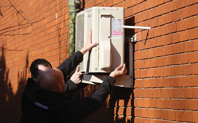
Figure 4
Mount the indoor unit to the wall
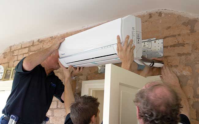
Figure 5
Connect refrigerant and drain hose pipes

Figure 6
Place control box cover back in reverse order
Share
Related articles

MACERATOR PUMPS
Macerator pumps offer the potential for installations where gravity drainage is not an option